Quantcast
Channel: GNS3 Labs | CCNP | CCNA Labs
Viewing all 113 articles
Browse latest View live

LACP with STP Sim | Switch practice Lab

$
0
0

Link Aggregation Control Protocol Configuration:

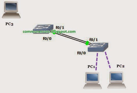
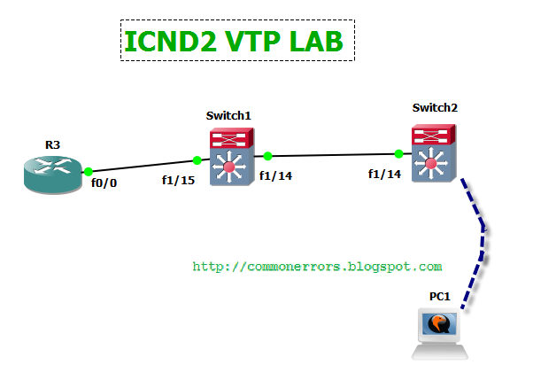
Suppose you have just added a new switch (SwitchB) to the existing network as shown in the topology.


RouterA is currently configured correctly for providing the routing function for devices on SwitchA and SwitchB. You need to be modified SwitchA to support the addition of SwitchB. You have been tasked with competing the needed configuring of SwitchA and SwitchB. SwitchA and SwitchB use Cisco as the enable password.

Configuration Requirements for SwitchA

  • The VTP and STP configuration modes on SwitchA is correct and should not be modified. 
  • You need to configure SwitchA as root switch for vlans 11, 12, 13, 21, 22 and 23. All other vlans should be left are their default values.

Configuration Requirements for SwitchB

You need to configure the VLANs according to following information:

VLAN#

VLAN NAME

VLAN Ports

21

HR

Fa1/9 and fa1/10

22

Finance

Fa1/5 and fa1/6

23

Marketing

Fa1/15 and fa1/14


– Access ports that assigned to VLANs should transition immediately to forwarding state upon detecting the connection of a device.
– SwitchB VTP mode needs to be the same as SwitchA.
– SwitchB must operate in the same spanning tree mode as SwitchA. And no routing is required on this Switch
–SVI vlan 1 is to be configured with IP address 192.168.1.11/24.

Inter-switch Connectivity Configuration Requirements:

- For operational and security reasons trunking should be unconditional and Vlans 1, 21, 22 and 23 should tagged when traversing the trunk link.
– The two trunks between SwitchA and SwitchB need to be configured in a mode that allows for the maximum use of their bandwidth for all vlans. This mode should be done with a non-proprietary protocol, with SwitchA controlling activation.
– Propagation of unnecessary broadcasts should be limited using manual pruning on this trunk link.


Answer and Explanation:

Some useful commands that may help you to find out the necessary information on SwitchA are as following:

show vtp status(you can get the information about VTP status on SwitchA i.e. SwitchA is in transparent mode)

show spanning-tree (rapid-pvst mode on SwitchA)

show vlan (check the native vlan and the existence of vlan100)

show etherchannel 1 port-channel and show ip int brief (check if Port-channel 1 has been created and make sure it is up)

show run (for complete configuration of Switch)


Configure the SwitchA as root switch for vlans 11, 12, 13, 21, 22 and 23 and need to have the same configuration as the SwitchB for successful configuration.

SwitchA>enable

SwitchA #configure terminal

SwitchA (config)#spanning-tree vlan 1,11,13,21,23 root primary

SwitchA (config)#vlan 21
SwitchA (config-vlan)#name HR
SwitchA (config-vlan)#exit

SwitchA (config)#vlan 22
SwitchA (config-vlan)#name Finance
SwitchA (config-vlan)#exit

SwitchA (config)#vlan 23
SwitchA (config-vlan)#name Marketing
SwitchA (config-vlan)#exit
SwitchA (config)#interface range Fa1/3 – 4
SwitchA (config-if-range)#switchport mode trunk
SwitchA (config-if-range)#switchport trunk native vlan 100
SwitchA (config-if-range)#switchport trunk allowed vlan 1,21,23
SwitchA (config-if-range)#channel-group 1 mode active
SwitchA (config-if-range)#channel-protocol lacp
SwitchA (config-if-range)#no shutdown
SwitchA (config-if-range)#end

——————————————————————————————–

Configuration VLANs according to given table:
SWITCHB#configure terminal

SWITCHB(config)#vlan 21
SWITCHB(config-vlan)#name HR
SWITCHB(config-vlan)#exit

SWITCHB(config)#vlan 22
SWITCHB(config-vlan)#name Finance
SWITCHB(config-vlan)#exit

SWITCHB(config)#vlan 23
SWITCHB(config-vlan)#name Marketing
SWITCHB(config-vlan)#exit
SWITCHB(config)#vlan 100
SWITCHB(config-vlan)#name TrunkNativeVlan

SWITCHB(config-vlan)#exit
SWITCHB(config)#interface range Fa1/9 – 10
SWITCHB(config-if-range)#switchport mode access
SWITCHB(config-if-range)#switchport access vlan 21
SWITCHB(config-if-range)#spanning-tree portfast (
Access ports that assigned to VLANs should transition immediately to forwarding state upon detecting the connection of a device.)
SWITCHB(config-if-range)#no shutdown
SWITCHB(config-if-range)#exit

SWITCHB(config)#interface range Fa1/5 – 6
SWITCHB(config-if-range)#switchport mode access
SWITCHB(config-if-range)#switchport access vlan 22
SWITCHB(config-if-range)#spanning-tree portfast
SWITCHB(config-if-range)#no shutdown
SWITCHB(config-if-range)#exit

SWITCHB(config)#interface range Fa1/14 – 15
SWITCHB(config-if-range)#switchport mode access
SWITCHB(config-if-range)#switchport access vlan 23
SWITCHB(config-if-range)#spanning-tree portfast
SWITCHB(config-if-range)#no shutdown
SWITCHB(config-if-range)#exit

SwitchB VTP mode needs to be the same as SwitchA:

SWITCHB(config)#vtp mode transparent

SWITCHB(config)#spanning-tree mode rapid-pvst

Configure VLAN-1 with IP address 192.168.1.1:

SWITCHB(config)#interface vlan 1
SWITCHB(config-if)#ip address 192.168.1.11 255.255.255.0
SWITCHB(config-if)#no shutdown
SWITCHB(config-if)#exit


Vlans 1, 21, 22 and 23 should tagged when traversing the trunk link:

SWITCHB(config)#interface range Fa1/3 – 4
SWITCHB(config-if-range)#switchport trunk encapsulation dot1q

SWITCHB(config-if-range)#switchport mode trunk
SWITCHB(config-if-range)#switchport trunk native vlan 99
SWITCHB(config-if-range)#switchport trunk allowed vlan 1,21-23


Maximum use of bandwidth for all vlans with SwitchA controlling activation:
SWITCHB(config-if-range)#channel-group 1 mode passive //mode passive because “SwitchA controlling activation”
SWITCHB(config-if-range)#channel-protocol lacp
SWITCHB(config-if-range)#no shutdown
SWITCHB(config-if-range)#end


STP Switch Sim | Spanning Tree priority Configuration

$
0
0
Question:

A company has an existing network comprised of 5 switches; 
·         CoreSwitch
·         DSW1
·         DSW2
·         AcessSwitch1
·         AcessSwitch2
This switch network has pre-VLAN spanning tree mapping. You has the following tasks to complete this Lab:

CoreSwitch should be the root bridge for VLAN 20, but currently DSW1 is the root bridge for VLAN 20.
Traffic for VLAN 30 should be forwarding over the gig 1/0/6 trunk port between DSW1 and DSW2. However VLAN 30 is currently using gig 1/0/5.
Traffic for VLAN 40 should be forwarding over the gig 1/0/5 trunk port between DSW1 and DSW2. However VLAN 40 is currently using gig 1/0/6.

You task is complicated by the fact that you only have full access to DSW1, with the enable password cisco. You are allowed and provided only limited show commands access is provided on CoreSwitch, and DSW2 using the enable 2 level with a password of Cisco. You are not allowed to made configuration changes on these Switches.  Also you don’t have access to ASW1 or ASW2. So you are only limited to make configuration on DSW1.

Required Configurations and Explanation:  

1.  “CoreSwitch should be the root bridge for VLAN 20.
DSW1 is currently the root bridge for VLAN 20″ our task to make CoreSwitch the root bridge for VLAN 20. For making the CoreSwitch as a root bridge we need to assign the lowest priority value for VLAN 20 on CoreSwitch, but we are not allowed to make changes on this Switch we have only access to DSW1 therefore we can increase the priority of DSW1 so that it become higher than CoreSwitch. For this use the“show spanning-tree” on CoreSwitch and on DSW1 for checking the priority of both switches for VLAN 20. Currently DSW1 is the root bridge for VLAN 20 (notice the line “This bridge is the root” on below figure).


DSW1>enable
DSW1#show spanning-tree

To make the CoreSwitch the root bridge we need to increase the DSW1′s priority value, the best value should be you can use another value but make sure it is higher than the CoreSwitch priority value by checking if the CoreSwitch becomes the root bridge or not; and that value must be in increments of 4096.


DSW1#configure terminal
DSW1(config)#spanning-tree vlan 20 priority 61440 
2.“Traffic for VLAN 30 should be forwarding over the gig 1/0/6 trunk port between DSW1 and DSW2.
VLAN 30 is currently using gig 1/0/5″ and gig 1/0/6 is in blocking state, you can find these information by using command “show spanning-tree”. We know that spaning tree protocol make the forwarding port base on

  •   Bridge-ID
  •  Port-Cost
  • Interface-ID


Since both ports have same bridge-ID and both interfaces are fastethernet therefore they will have the same port-cost. When the both ports have same port-cost and bridge-ID then the port with the lower interface will be in forwarding state while other will be in blocking state. Same happen in this case that both switches DSW1 and DSW2 have same bridge-ID and Cost therefore gig 1/0/5 is forwarding port for VLAN 30. Now you can make the gig 1/0/6 as forwarding port by lowering the Priority Number of the port gig 1/0/6 you can see the currently priority numbers of ports by show “show spanning-tree


Notice that we only need to change this value for VLAN 30, not for all VLANs.

DSW1(config)#interface g1/0/6
DSW1(config-if)#spanning-tree vlan 30 port-priority 64
DSW1(config-if)#exit

“3. Traffic for VLAN 40 should be forwarding over the gig 1/0/5 trunk port between DSW1 and DSW2.

However VLAN 40 is currently using gig 1/0/6″ and our task is to make the forwarding of VLAN 40 through gig 1/0/5. It is a similar job, but we are not allowed to make any configurations on DSW2, and in this case we can’t change the port-priority for VLAN 40. There is another solution for this you can change the cost (set the lower value) on an interface of DSW1 then only DSW1 will learn the change.

By default, the cost of a 100Mbps link is 19 but we can change this value to make sure that VLAN 40 will use interface Gig1/0/5.

DSW1(config)#interface g1/0/5
DSW1(config-if)#spanning-tree vlan 40 cost 1
DSW1(config-if)#exit

You should re-check to see if everything was configured correctly:
DSW1#show spanning-tree

DSW1#copy running-config startup-config

Backup, Load n restore Router Configuration in Text file via TFTP on GNS3

$
0
0

Backup router configuration with TFTP-server: 

In this article i will show you that how you can save router configuration to text file or restore router configuration from a text file from your PC to your real router or on a GNS3-router. I am showing this simulation on GNS3 for this purpose we required TFTP Server. TFTP server installation and configuration are very simple and easy, install it from its setup.exe and in configuration of TFTP server you need to define it's IP address and file-path of TFTP-server.
  • IP address of tftp-server will be IP address of your PC 
  • Path of TFTP server is the default location where you can save and load the configuration file to router.
You can review my TFTP configurations, 192.168.1.2 is IP of my PC.
For GNS3 simulation i used a "cloud" for connecting tftp-server to GNS3 router, i just mapped the physical network interface with cloud from its configuration and assign the IP address to router interface from same IP-range i.e. 192.168.1.112.


How to install a text file configuration into a Router:

Suppose you have a configuration file (named:router-config)on your computer (Placed at default path of tftp-server). You can copy configuration file from PC to GNS3-router using TFTP. You can perform this task with following commands:

Coyp configuration to Running-config:
Router#copy tftp://192.168.1.2/router-config running-config
where 192.168.1.2 is address of tftp-server, "router-config" is text configuration file which you want to import on gns3 router.

Coyp configuration to Startup-config:
Router#copy tftp://192.168.1.2/router-config startup-config

Backup Startup or running configuration of Router to a TFTP Server on GNS3:

Now suppose you want to save your router configuration to text file, you might perform this task to back up a current configuration file to a server before changing its contents, thereby allowing you to later restore the original configuration file from the server. You can save both your startup and running configuration to your PC using TFTP-server by using following commands:


Router#copy running-config tftp:                              (type the command n press enter)
Address or name of remote host []? 192.168.1.2       (address of tftp-server) 
Destination filename [router-confg]? tftp-config       ("tftp-config" is configuration file name which will be create on tftp-server, you can use any other name)

For saving startup configuration:

Router#copy startup-config tftp:
Address or name of remote host []? 192.168.1.2
Destination filename [router-confg]? startup-config


Cisco 3725 IOS Image Free Download for GNS3

$
0
0

Router IOS image with Switching Functionality:

Cisco 3700 series routers can provide you the different services like Security, Voice, IP Telephony, voice mail, Video and Content Networking in your network.


Key features for the Cisco 3725 include:


  •          You can  use16-port EtherSwitch NM with 3725 which can provide you the switching functionality.
  •        Support for all major WAN protocols and media: leased line, Frame Relay, ISDN, X.25, ATM, fractional T1/E1, T1/E1, xDSL, T3/E3, HSSI
  •      You can enable the SSH because of it's k9(crypto) feature.How to enable SSH on your router in GNS3


You can download 3725 gns3 router IOS from here and play it on GNS3 for learning purposes. You can perform different routing labs as well as switching labs with this IOS image.

How to enable SSH on router Switch on GNS3 | Configuring Secure Shell Cisco

$
0
0

CLI configuration of SSH on Cisco Router/Switch

Secure Shell (SSH) is a protocol like telnet which provides you a secure remote connection to network devices. Telnet communication is in clear text and a hacker can capture your login information and other contents using a packet sniffer. Whereas SSH creates an encrypted communications tunnel between you and the router. There are two types of SSH i.e.
  • SSh version 1
  • SSH version 2

Now a day’s everyone is using version 2 because it is more secure and have better encryption algorithm.
In this GNS3 lab I will show you that how you can configure your router or switch for SSH access, you need a k9(crypto) IOS image for SSH configuration. I have used 3725 IOS you can download it from this link: k9(crypto) Cisco IOS image


Lab Objective/Task:

1.       Configure SSH communication on L3_Switch.


The topology is simple and our task is to configure SSH on L3_switch, we need the following steps on L3_Switch for accomplish this:
Configure the hostname:

Router#Enable
Router#config t
Router#(config)hostname L3_Switch
Telnet does required only the password where as SSH uses both username and password. Therefore we need to create a user for SSH.
L3_Switch#(config) aaa new-model
L3_Switch#(config) username admin secret 5 cisco(“secret” uses the MD5 hash in running config,where 5 Specifies a HIDDEN secret will follow and Cisco is the hidden password)


Configure the DNS domain:

L3_Switch#(config)ip domain name cisco.com
Enable SSH:

L3_Switch#(config) crypto key generate rsa

How many bits in the modulus [512]:

(If you can want to enable 512 bits encryption then press enter otherwise you can type the other values like 1024 etc.)

L3_Switch#(config)#ip ssh version 2
L3_Switch# (config)#line vty 0 4
L3_Switch# transport input SSH
L3_Switch# (config-line)#login local

Testing:

You can test SSH configuration from R2 by accessing L3_switch by SSH with following command:

ssh -l admin 192.168.72.100

Set / sync router Clock With NTP Server on GNS3

$
0
0

How to sync router time from internet?

The Network Time Protocol (NTP) is a protocol used for synchronizing the clocks of network devices over data networks.  In Cisco router sometimes obtaining the correct time is extremely important because a variety of services depend on it. The logging service shows each log entry with the date and time so for the accurate data you need the updated time and date at every time. Similarly in configuring some routing protocol’s authentication you also need to have the updated and accurate time on the every router on which you want to enable the authentication. You can sync your router’s time and date with NTP server. You can use some internet NTP server or own master NTP server from within your internal network if you have.  In this gns3 lab we will learn that how we can perform NTP configuration on Cisco router and can sync your router time with the internet NTP server.


In this lab we have three routers R1, R2 and R3. R1 is connected to internet.


Labs Objectives:

·         Configure R1 for automatically sync its time from internet NTP sever and configure as NTP master.

·         Configure R2 and R3 as NTP client and enable them to update their time from R1.


For configuring this gns3 lab you need internet connectivity for accessing the live NTP server from your internal GNS3 router. For providing the internet connectivity on R1 you have to add a cloudfor network nodes in gns3 then associate your physical network interface with it, e1/0 is the interface that is connected to your physical interface (cloud) so you must assign IP address from same subnet that your physical interface have. Since my physical interface has IP 192.168.1.3/24 with gateway 192.168.1.1 therefore I have assign 192.168.1.11 to e1/0.

R1 configuration:

enable

config t

interface e1/0

ip address 192.168.1.11 255.255.255.0

no shutdown

exit

ip route 0.0.0.0 0.0.0.0 192.168.1.1 (for providing internet access)


After the above configuration you must able to ping your gateway and any internet address.

NTP configuration:


You can find IP address of live NTP server by pinging “pool.ntp.org”

R1(config)# Ntp server 202.125.132.12


R1(config)#ntp server master

You can verify the NTP configuration by following commands:

R1(config)#show NTP status

R1(config)#show ntp clock


R1(config)#show ntp association 

Following configuration create the connectivity with R2 and R3.

R1(config)#inter e1/1

R1 (config-if)#ip address 11.11.11.1 255.255.255.0

R1 (config-if)#no shut

R1 (config-if)#inter e1/2

R1 (config-if)#ip address 12.11.11.1 255.255.255.0

R1 (config-if)#no shut


R2 and R3 configuration:

Configure R2 and R3 as NTP client and enable them to update their time from R1.


R2(config)#inter f0/0

R2(config-if)#ip address 11.11.11.2 255.255.255.0

R2(config-if)#no shut


R2(config)#ntp peer 11.11.11.1


show ntp status

GNS3 vlan configuration is not saving: Vlan database lost when restarting

$
0
0

Saving vlan.dat in nvram instead of Flash:

By default all Vlan information is store in “vlan.dat” file which exists in flash. Therefore when you restart the GNS3-switch you lost all vlan configurations, gns3 by default doesn’t allow you to save or edit vlan database because of limit flash in gns3 router and result in following error:
   

Error: “ not enough space on flash to store vlan database. Trying squeeze…

Squeeze of flash complete

not enough space on flash to store vlan database even after squeeze

Error on database apply 40: NV storage failure”


Steps for saving Vlan Configuration in Gns3:

But there is a following way, by using this you can save Vlan configuration in Gns3 and can also change vlan.dat path from flash memory to nvram in gns3 router.


switch#erase flash

switch#squeez flash


switch#config t

switch(config)#ntp file nvram:vlan.dat (this command will tell Gns3 router to save VLANs in NvRam)

For testing and confirmation:

create some vlan and then confirm with these commands:

show vlan-switch


switch#dir nvram


EtherChannel | Lag port or link aggregation configuration on GNS3

$
0
0

Port channel interface:


Using port channel interface group you can perform the same configuration at once, you need to configure all your configuration on your channel group and then it will replicate all your configuration on all the interface that you have added to that channel group.


With port aggregation you can utilize your interface with maximum throughput and speed. Suppose you have two redundant interfaces between your switches, using channel group you can utilize both interfaces at once. If you have two links of 1G each between two switches, you don’t get the 2G bandwidth/speed with channel group but you can used both link as once. In absence of channel group spaining tree protocol block one of link and use only one link/interface at a time. But with port channel if you have two PC with switch as shown in figure, then PC1 may use interface 0/1 and PC2 may use other interface a, in this way you can utilize both of your interfaces. EtherChannel provides automatic recovery for the loss of a link by redistributing the load across the remaining links. If a link fails, EtherChannel redirects traffic from the failed link to the remaining links in the channel without intervention.
 

How to configure Port channel group:
Commands:


interface range f1/0 - 1

channel group 1 mode on

 For configuring different setting with port channel you can use following configurations:

interface port-channel 1

switchport speed 4000

no shut


When you created the channel group then it is necessary that you should perform all your configuration through that channel-group if you do some configuration on individual interfaces then it will give you error of ”mismatch configuration”..


Find the MAC address on Cisco router, IP phone & computer

$
0
0

How to find MAC address of computer on windows 7,8 XP


How to know the address MAC (MediaAccess Control) of your computerThis information is required for certain operations such as taking remote control.


MAC stands for: “Media Access Control”. This is the address of a network card and it is specific to each network device and it is encoded in hexadecimal. It is located in layer 2 of the OSI model (interconnecting computer networks) or TCP / model IP (Internet), and is fixed during manufacture.

You can find the MAC address of any computer on windows 7 or 8 by using command “ipconfig /all”.

Open command prompt by typing cmd in runand then type ipconfig /all, this will show you the all address of network card that are attached with your PC. You can see your MAC address under the title “physical address”.


Find MAC Address on a Cisco VoIP Phone:

Following are the simple steps for locating the MAC address on a VoIP device.

1.       Open the phone settings or press the Settings button on the VoIP phone.
 
2.       By using buttons and softkeys on the IP phone, select Network Configuration. 
3.       Enter into Network Configuration.
 
There, you will find the MAC Address appears option.

Find MAC address of Cisco router interface:

Each Ethernet interface on a router will have a MAC address (as opposed to some other layer-2 transport interface).  The MAC address used will vary based on the hardware platform and/or configuration. You can find the MAC address by using command “show interfaces <interface-name>”e.g. show interfaces fastEthernet 0/0


How to decoding or get a level 7 (enable secret) password on Cisco Router | services password-encryption

$
0
0

How to convert the Cisco enable secret password into plain text:


This article is only for learning purposes in which I ll show you that how you can decode a Cisco enable secret password into clear text. When the "password-encryption service" is enabled on a router or switch, then the “show running config” command will shows an encrypted password using a hash algorithm as shown in figure that will hide your real password.


You can revert this password with different utilities or using some on-line websites.


So let's start by setting up a password in the clear text:

R1 (config) # line console 0
R1 (config-line) # password Ci$co
R1 (config-line) # login
R1 (config-line) # exit

Of course, the password appears in clear text in the running-config ...


Now you can encrypt this password using password-encryption service", you can use the following command for this purpose:

R1 (config) # services password-encryption
The password is now encrypted and therefore unreadable in the configuration ...


If you want to decode the password, you can use following website that offers this feature:

http://packetlife.net/toolbox/type7/

you can put the hash in type 7 hash field and then click on reverse and you are done.


Download Cisco 1700 series router IOS for Gns3

$
0
0
Advertisement:

Gns3 IOS image of Cisco 1700 series:


You can download 1700 series router IOS for Gns3 from here and can use it for your GNS3 for performing different gns3 labs for learning purposes.

The Cisco 1700 Series Modular Access Router are ideal for LAN and small networks, you can build a fast, reliable, and secure Internet and network access through these routers.
Please notes that you can use these IOS Image only in Gns3 topologies, in other scenarios these images may not work.


IF this not work for you then you can try the following one...!


How to add IOS image in GNS3 0.8.6 on Ubuntu 14.04

$
0
0

How to use IOS image in Gns3 0.8.6 on Linux:

This is a basic article related to Gns3 in which I ll show you that how you can add different IOS images of routers and switches in gns3 version 0.8.6 for performing different routing labs and switching labs.

1. Open “IOS images and Hypercvisors” for edit menu.


2. browse for the image file in Image file and select the platform like 1700, 2600 or 3600 according to your IOS, then select the Model of your Cisco router. Click save for saving IOS.


3. For using this IOS into Gns3 typologies click on router symbol in upper left corner of GNS3 and  drag the desire router IOS on dashboard. Similarly you can use switches and qemu host IOS in same way.


Add Router IOS in GNS3 1.0 beta2

$
0
0

How to run the IOS devices on GNS3 1.0 beta2:

Now GNS3 start introducing its new versions with new features and with some major changes and also remove the different bugs from previous versions. GNS3 1.0 beta2 is one of them. today, i have tested this version of GNS3 on windows 8.1, it works great for me and have very nice improve user interface. But this new user interface waste my time for searching the "ios image and hypervisors" for adding IOS images to GNS3.... :D

ios image and hypervisors menu is remove from this new version and has been introduced a new tab IOS routers for adding binary IOS to GNS3. For adding IOS in GNS3 1.0 you can follow these steps:


  1. Open the Edit\preferences  
  2. here you can find a tab IOS routers on left side, click on it and browse the IOS images from "IOS path" and then click the save button for saving that image.


ICND1 Practice LAB with RIPv2 SIM on GNS3

$
0
0

Configure different passwords and RIP on Cisco Router (ICND1 100-101):

This is most basic and simple lab for preparing ICND1 exam, which will test your skills related to different password configurations and RIPv2 on Cisco router.

You need to complete the configuration on newly installed router “Florida” in below network-diagram, RIPv2 is running on other router so you need to complete following configuration for making communication possible among Florida andnewyork router:

  1. Set the name of router to Florida
  2. Set the enable-secret password of Florida to icnd1
  3. Set the global configuration password to icndpass
  4. Configure vty password (telnet) to ICND1VTY
  5. Assign the first useable IP address to Ethernet interface Fa0/0 from subnet 192.168.1.0/27 
  6. Assign the last IP address to serial interface S0/0 from subnet 200.1.1.128/28 
  7. Advertise above two subnets via RIPv2 routing protocol on Florida.

Solution:

If you want to practice this lab in GNS3 then you can download router (newyork) configurations  from here and can complete the remaining lab according to following configurations.

1. Change Host name of Router to Florida:
R1#enable

R1#config t
R1(config)#hostname Florida


2. Set the enable-secret password of Florida to icnd1:

Florida(config)#enable secret icnd1


3. Set the global configuration password of router:

Florida(config)#line console 0

Florida(config-line)#password icndpass

Florida(config-line)#login

Florida(config-line)#exit

4. Configure vty password (telnet) of router:

Florida(config)#line vty 0 4

Florida(config-line)#password ICND1VTY

Florida(config-line)#login

Florida(config-line)#exit


5. Configure Ethernet interface f0/0 of Router:

For assigning the first useable IP address to Ethernet interface from subnet 192.168.1.0/27 you need to find subnet-mask and IP ranges (increment):

Subnetting for Class C address

Bit# in 4th octet

25

26

27

28

29

30

31

32


IP ranges/ increment

128

64

32

16

8

4

2

1


Since the first three bits are ‘1’ or "on" in 4th octet for given 192.168.1.0/27 and we know that the default subnet-mask for class-C is 255.255.255.0 you can find the subnet-mask for this subnet by adding first three bits i.e. 128+62+32=224 so

Subnetmask=255.255.255.224 

From above table you can find that IP range for /27 is 32 so we have following subnetwork for this subnet with a difference of 32:


Subnetwork1= 192.168.1.0 to 192.168.1.31

Subnetwork2= 192.168.1.32 to 192.168.1.63

.

.

.
.


Our give subnet belong to Subnetwork1= 192.168.1.0 to 192.168.1.31 so we have

Subnet ID = 192.168.1.0

Broadcast address=192.168.1.31

Useable IP range= 192.168.1.1 to 192.168.1.30


From above calculation we have the first useable IP address 192.168.1.1 and subnet-mask 255.255.255.224 so let assign this IP address to router interface:


Florida(config)#interface f0/0

Florida(config-if)#ip address 192.168.1.1 255.255.255.224

Florida(config-if)#no shu


6. Configure serial interface s0/0 of Router:

For finding the last IP address for 200.1.1.128/28 you can use the following table:

Subnetting for Class C address

Bit# in 4th octet

25

26

27

28

29

30

31

32


IP ranges/ increment

128

64

32

16

8

4

2

1


128+62+32+16=240

By adding the first 28 bit you can get the subnet-mask= 255.255.255.240

For find IP last IP address you need to have the all useable IP address for subnet200.1.1.128/28, with /28 you have the following sub-network with increment of 16.

Subnetwork1=200.1.1.0

Subnetwork2=200.1.1.16

Subnetwork3=200.1.1.32

Subnetwork4=200.1.1.48

Subnetwork5=200.1.1.64

Subnetwork6=200.1.1.80

Subnetwork7=200.1.1.96

Subnetwork8=200.1.1.112

Subnetwork9=200.1.1.128 to 200.1.1.143

Subnetwork10=200.1.1.144


From above calculation we find that our network belong to Subnetwork9=200.1.1.128 to 200.1.1.143 with following details:

Subnet ID= 200.1.1.128

Broadcasar Address= 200.1.1.143

Useable IP addresses= 200.1.1.129 to 200.1.1.142


So last IP address is 200.1.1.142 and subnet-mask is 255.255.255.240


So configuration for serial interface is as following:


Florida(config)#interface s1/0

Florida(config-if)#ip address 200.1.1.142 255.255.255.240

Florida(config-if)#no shut

7. Configure RIPv2 on router:


Florida(config)#router rip
Florida(config-router)#version 2
Florida(config-router)#network 192.168.1.0
Florida(config-router)#network 200.1.1.128

You can test your configuration by ping from florida-router to 10.1.1.10 which should be successful.


New OSPF sim for ICND1 on GNS3 | 100-101 Practice Lab

$
0
0

OSPF Lab on GNS3 for ICND1: 


In network diagram you can find the three router R1, R2 and R3. R1 and R2 are already configured with IP addresses and OSPF area 0. You need to perform the following tasks and configurations:

  1. Configure last available IP address of f0/0 of R3 with first usable subnet 192.168.224.0/28
  2. Configure first available IP address for S1/0 with second usable subnet from the network 192.168.224.0/28.
  3. Configure OSPF with area 0 on R3 so that R3 can properly communicate with R1 and R2 


Solution:

You can practice this LAB on GNS3 by downloading R1 and R2 configuration other necessary detail for GNS3 configuration are as under:


Router IOS= 7200 series (you can download it from here)

GNS3 version= GNS3 1.0 beta2

Router module/slot used: slot1=c7200-IO-2FE, slot2=PA-8T

(Note: for quick configuration you can download these text files and can copy paste these configuration into your GNS3 router)


Configure f0/0 with first useable subnet from 192.168.224.0/28:


For finding the first useable subnet you can consider the following table:

Subnetting for 192.168.224.0/28

Bit# in 4th octet

25

26

27

28

29

30

31

32


IP ranges/ increment

128

64

32

16

8

4

2

1


From above table you can find following subnets with the increment of 16 for 192.168.224.0/28.


Subnet1= 192.168.224.0 to 192.168.224.15               (Subnet ID=192.168.224.0)
Subnet2= 192.168.224.16 to 192.168.224.31             

(Subnet ID=192.168.224.16)
Subnet3= 192.168.224.32 to 192.168.224.47             

(Subnet ID=192.168.224.32)
.
.
.

Since we need to assign last available IP address from subnet1, therefore we have the last IP address= 192.168.224.14


R3> enable
R3# config t

R3(config)# int f0/0

R3(config-if)# ip address 192.168.224.14 255.255.255.240

R3(config-if)# no shut


2. Configure first available IP address to S1/0 with second usable subnet from the network 192.168.224.0/28:

For above table we have already find that second subnet is 192.168.224.16 to 192.168.224.31 with first IP address=192.168.224.17


R3(config)# int S1/0

R3(config-if)# ip address 192.168.224.17 255.255.255.240

R3(config-if)# no shut


3. Advertise both interface of R3 in OSPF:

You can advertise these two subnet on R3 using Subnet-IDs by following commads:


R3(config)#Router OSPF 1

R3(config-router)#network 192.168.224.0 0.0.0.15 area 0

R3(config-router)#network 192.168.224.16 0.0.0.15 area 0


Results and testing:

After the correct configuration you should have the following output for “show IP route” command:


After the configuration you should have successful ping to 192.168.200.1


If you have any trouble/issue with R3 configuration you can also download R3 configuration from here and can compare it to your configuration.


Configure VPCS IP address and Gateway on GNS3 1.1

$
0
0

How to use VPCS in GNS3 and how to configure IP address and Gateway for it:

VPCS is virtual PC simulator that is now included in GNS3 devices. You can use it for testing purposes on GNS3, you can ping, traceroute etc with VPCs on GNS3.
VPCs is already included in GNS3 1.1 and some earlier versions and also you don't need to perform any additional setting for it. In following figure you can find the default settings of VPCs on GNS3 1.1, which normally works great..!

how to simulate PC with VPCs on Gns3:

Drag the VPCS from end-device on Gns3 dashboard, right click on it and then on start.

It will boot in few seconds. For configuring IP address and gateway right click on VPCS and then on console.  You can use the following command for configuring IP address and gateway for this virtual PC.

IP <address> [/<mask>] [<gateway>]

For example if you want to assign IP address "192.168.2.1" with subnet-mask 255.255.255.0 and gateway "192.168.2.2" you will use the following command:

PC1> ip 192.168.2.1 /24 192.168.2.2


For connectivity test you can use ping command


Following are some other ways of simulation of Host or PC with GNS3


Nat Sim for ICND2 Practice lab on GNS3

$
0
0
Question

Your company has 14 PCs those need to access the internet simultaneously. All the computers in the local area networkare using the private IP addressesfrom 192.168.2.1 to 192.168.2.14.

  • Configure serial s0/0 as NAT outside
  • Configure serial f0/0 as NAT inside
  • You need to configure NAT (network address translation)on PE-router with 4 public IP addresses from 192.168.1.107 to 192.168.1.110 so that all the hosts can use internet at the same time.

Note: Since we are creating this lab on GNS3 therefore we are using private IP addresses i.e. 192.168.1.X for NAT translation instead of real Public IPs. Please keep in mind that in real scenario you must use Public IP addresses. 

For configuring this lab on GNS3 1.1 i have used the following devices:

Router: 
IOS: c7200-jk9s-mz.124-13b.image
Router full configuration: PE-Router configuration

Cloud:
I have used cloud for internet connectivity with my laptop Ethernet interface, i also recommend you to use physical local area connection of your PC with gns3-cloud instead of wifi-adapter, you learn how to use cloud in GNS3 from here.

VPCS (Virtual-Host):
IP adress=192.168.2.1
Gatway= 192.168.2.2
You can learn how to configure IP address and Gateway of VPCS on gns3 from here.

Solution:

1.Configure serial f0/0 as NAT inside 

Router>enable 
Router#
config t
Router(config)#hostname PE-router
PE-router(config)#interface fa0/0 
PE-router(config-if)#ip nat inside 
PE-router(config-if)#
exit 

2.Configure serial s0/0 as NAT outside


PE-router(config)#interface s0/0 
PE-router(config-if)#
ip nat outside 
PE-router(config-if)#
end

3.Configure NAT ON Router:

In second step you need to configure pool of Public IP addresses, you can do it by using following commands:

PE-router(config)#ip nat pool LIVEIP-POOL 192.168.1.107 192.168.1.110 netmask 255.255.255.248


Now create an access-list for private IP addresses and permit all hosts.

PE-router(config)#access-list 1 permit 192.168.2.0 0.0.0.15

Now apply this access-list with NAT, following command will pick up IP address from 192.168.2.1 to 192.168.2.14 and with map it to LIVEIP-POOL (200.200.200.105 to 200.200.200.110)

“Overload” keyword allows to map multiple IP addresses to a single registered IP address by using different ports.

PE-router(config)#ip nat inside source list 1 pool LIVEIP-POOL overload

Save all configurations;

PE-router#copy run start

Testing:

 Ping 192.168.1.1 or some internet address like 4.2.2.2 and then see the nat translations using "show ip nat translations"
PE-router# show ip nat tran

how to use virtualBox VM with GNS3 1.1 | VM Lab

$
0
0

How to use VirtualBox Virtual Machine in GNS3 as Virtual Host in GNS3 Topologies:

You have different options for simulating Virtual PC on GNS3 which are listed below:


In all above methods, simulating a PC with VirtualBox is very handy which provide you more options as compare to others. In-fact you have a real PC with operating  system of your choice with full control.
In this article i will show you how to use Windows 7 VM with GNS3. Following are the step by step process of configuring VM in GNS3:

1. Create or install any virtual machine in VirtualBox. I already have an installed VM i.e. "Win 7" so i will use this for lab.
2. Now open the GNS3 1.1 and go to Edit\Preferences and from VirtualBox VMs menu create a new VM by clicking the New button.


3. Select the desire Virtual Machine from next menu, i am selecting the only created VM "win 7" and then click finish.
4. Once you finished, you can find your VM in GNS3 devices.

5. Drag the "win 7" VM on Dashboard, i have created the following topology with this VM.
6. Right click on VM and click start, GNS3 will start booting Windows 7 with help VirtualBox. Once it is booted, now you can configure IP address for it. Open local area connections properties and double click on internet protocol version 4

and assign the IP address and gateway.

Watch a Video how to use VM on GNS3


how to use or configure virtualBox VM with GNS3...by Waqasgk


ICND2 VTP GNS3 Configuration LAB

$
0
0

How to configure Vlan Trunking Protocol on Gns3

Question

This GNS3 lab is related to VLAN Trunk Protocol, in which you have two switches Switch-1 and Switch-2 and you need to configure the Switch-2 according to following requirement:

  1. Determine and configure the gateway and last IP address on vlan-interface from subnet 192.168.33.32\27
  2. Find and configure the same VTP domain on switch-2 as on Switch-1. (Switch-1 has the domain “City-Campus”)
  3. Configure Switch-2 as VTP Client


Solution: how to configure this Lab:

You can configure this on GNS3 very easily, according to question Router and Switch-1 are already configured. You can complete this lab by creating the above topology in GNS3 and then you can download routerandswitch-1configurations from here, paste them on router and switch-1 respectively and complete it with following configurations:

GNS3 version: 0.8

Switch IOS: C3725-AD.BIN downloadfrom here

Determine and configure the gateway and last IP address from subnet 192.168.33.32\27:

For finding the gateway and vlan IP address on Switch-1 you can use the command “show run


Switch-1#show running-config


From above out-put you can see that vlan-subnet on switch-1 is 192.168.33.50\27 and from subnetting you can find the valid IP addresses for this subnet:

Subnetting for Class C address

Bit# in 4th octet

25

26

27

28

29

30

31

32


IP ranges/ increment

128

64

32

16

8

4

2

1


From above table we have the following details:

Subnet ID= 192.168.33.32

Broadcast Address=192.168.33.63

Valid IPs= 192.168.33.33 to 192.168.33.62

So we have 192.168.33.62 the last IP address for given subnet.

Switch-2#config t

Switch-2(config)#int Vlan1
Switch-2(config-if)#ip address 192.168.22.62 255.255.255.224
Switch-2(config-if)#no shut


Switch-2(config-if)#exit
Switch-2(config)#ip default-gateway 192.168.22.35


Find and configure the same VTP domain on switch-2

For VTP domain of switch-1, you can use the “show vtp status” command on Switch-1.


switch-1#show vtp status


We have find that VTP-domain of switch-1 is “City-Campus”. For configuring the same domain you can use the following commands:

Switch-2#config t

Switch-2(config)#vtp domain City-Campus


Configure Switch-2 as VTP Client

You can set Switch02 as VTP client by using command: “vtp mode client” or "vtp client"


Real Switch Configurations

if you are configuring it on GNS3

Switch-2#config t

Switch-2(config)#vtp mode client

Switch-2(config)#vtp domain City-Campu

Switch2#vlan database

Switch2(vlan)#vtp client

Switch2(vlan)#vtp domain City-Campus


How to Test or Confirm lab configurations on GNs3:

Create some vlan on switch1, if your configurations are complete then it will automatically create that vlan on Switch2 as well. (Switch2 is VTP client therefore it will sync its vlan database from switch1 which is VTP server)

Switch1#vlan database

Switch1(vlan)#vlan 11


After creating vlan 11 on switch1, Show vlan-switchon switch2 should have following configurations:

If you have some issue with your lab then you can download Switch2 configuration from here and can compare with your for troubleshooting.

Download Juniper router IOS/Image for Gns3 JunOS Olive 12.1R1.9

$
0
0

Download VirtualBox Image (IOS) of Juniper Router for GNS3:

From here you can download "JunOS Olive 12.1" VM image, you can run it with GNS3 for simulating juniper router. (Please note that this image is only provide to you for informational purpose and for GNS3 use.)

What is JunOS Olive?
JunOS Olive is a juniper router software that you can use on PC. Initially Olive was used by Juniper internally for lab work, but now it become a source to learn the JUNOS CLI on a low-cost platform.

Download JunOS forGNS3:
You can actually run this JunOS on VirtualBox and then can simulate this into GNS3. You can Download this JunOS for Gns3 from following link and can perform and configure different lab on Gns3.


Download JunOS Gns3


Click on above link and then choose "download anyway" for download this file.


How to use JunOS Olive on Gns3


Viewing all 113 articles
Browse latest View live


Latest Images